production facility, plant layout
production facility, plant layout
The general procedure of defining a plant layout includes the verification and definition of:
- the product spectrum and workflow,
- the ideal case situation,
- a scale model of the area,
- a rough layout,
- fine planning the final layout.

facility layout
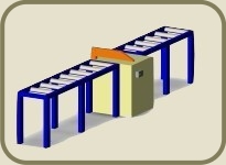
The facility layout is created in 3D, using a database of machines already created or if necessary making a very basic scale model of a machine that is in production.
The illustration to the right is a simple screenshot made in the CAD Software and not rendered or optimised in any way.
»The detail level is adjusted to the demands and needs of the customer. As much as necessary, as little as possible.«
A further advantage of creating a plant layout in 3D is the possibility of using the same data for factory simulation purposes. The files produced can be imported into modern simulation software using standard interfaces such as dxf, stl, etc..
Methods for plant layout planning
Methods used for planning a production layout can be divided into conventional graphical and heuristic mathematical methods.
Conventional graphical methods:
The main character of graphical methods is that these take place on a trial and error basis.
- Graphical alignment:
by moving and adjusting machinery in a virtual scale model of the facility results can be achieved fairly quickly. - Circular method:
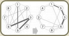
 The circular method, developed by ''Schwerdtfeger'' is a graphical method of planning a plant layout in which the machinery is positioned according to the main flow of material.
The ideal result in this case is a main material flow that is situated on the circle itself and the machines that are most dependant on each other are situated next to each other. The line strength indicates the amount of material to be transported.
Heuristic mathematical methods:
Mathematical methods usually have a equation that needs to be optimised e.g. the distance travelled or a cost formula that needs to be minimised.
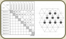
- modified triangular method:
 A prerequisite for this method is a transport matrix in which all stations, that a product has to pass, are accounted for. The matrix is then used to identify the main flow of material and ultimately used to position the manufacturing machinery.


